
Tinder Dating App: Meet & Chat
Contains adsIn-app purchases
3.6star
7M reviews
100M+
Downloads

Mature 17+
info


About this app
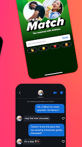
Match, Chat, and Date. That’s our mantra.
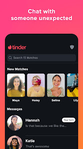
With 70+ billion matches to date, Tinder® is the top matchmaker dating app, and the best place to meet new people. Are you looking for true love? An open relationship? Are you looking to get out there and find a date, or do you just want to make friends and chat? With Tinder, you can meet local people everywhere and get the best out of your dating experience:
Whether you're straight, gay, bisexual, or anything in between, Tinder allows you to be who you are and find who you want.
Share your interests and learn more about your matches to get the conversation started, and get the sparks flying.
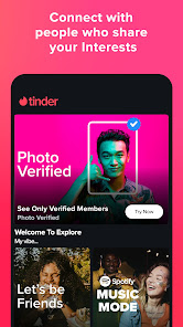
Photo Verified Profiles: Because the only surprises we want are flowers on the first date
Video chat: Test your online dating chemistry and meet new people from home!
Traveling somewhere? Get to know the singles from around the world. Dating in New York, meeting new friends in Miami, or going on a date in London: Wherever you go, we’ll be there.
Tinder Matchmaker - The Ultimate Friend Test
Discover the perfect way for potential matches to pass the friend test! With our newest feature, you can see who your friends Like for you. If ever in doubt or in need of a second opinion, use the Matchmaker feature to find the perfect match. Don't fret your match isn't all in their hands - whether your friend sends a Swipe Right™ or Swipe Left™, you still get to make the final call. What are you waiting for? Send your friend a matchmaker link and watch the story unfold!
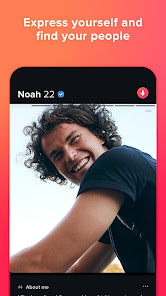
It’s easy and fun to meet new people on Tinder®. Make your profile stand out with your best pics and a little something about you to increase your match-making potential. Use the Swipe Right™ feature to Like someone, use the Swipe Left™ feature to Nope. And no pressure: With our double opt-in feature, the interest has to be mutual in order to be a match. How many dating apps can say that?
While you’re here — make a toast to the Gold life and enjoy some of Tinder’s premium features with our Tinder Gold™ subscription
♥ Likes You — see all your fans, saving you precious time
♥ Unlimited Likes for you to catch feelings for as many new people as you want
♥ Rewind — undo your last Like or Nope
♥Passport — find people online outside your zip code
♥ Monthly Boost — put your profile to the top for thirty minutes to get more attention
♥ 5 Super Likes available per week
Looking for access to all of Tinder’s premium features? Join Tinder Platinum™ to also get your Likes prioritized with potential matches, to be able to message before matching, and more.
There’s a plus side for those not ready to commit to a relationship with Gold or Platinum. With Tinder Plus®, you’ll unlock features including Unlimited Likes, Unlimited Rewinds, and Passport.
So what are you waiting for? Download the best matchmaker dating app today! It doesn’t matter if you’re looking to make friends, meet new people or find your perfect match, Tinder is a place where everyone can find exactly what they’re looking for. — and it’s about time you showed up.
-----------------------------------
If you choose to purchase Tinder Plus®, Tinder Gold™, or Tinder Platinum™ payment will be charged to your Google Play account, and your account will be charged for renewal within 24-hours prior to the end of the current period. Auto-renewal may be turned off at any time by going to your settings in the Play Store after purchase. No cancellation of the current subscription is allowed during the active subscription period. If you don’t choose to purchase Tinder Plus®, Tinder Gold™, or Tinder Platinum™, you can simply continue using Tinder for free.
All photos are of models and used for illustrative purposes only.
Privacy: https://www.gotinder.com/privacy
Terms: https://www.gotinder.com/terms
With 70+ billion matches to date, Tinder® is the top matchmaker dating app, and the best place to meet new people. Are you looking for true love? An open relationship? Are you looking to get out there and find a date, or do you just want to make friends and chat? With Tinder, you can meet local people everywhere and get the best out of your dating experience:
Whether you're straight, gay, bisexual, or anything in between, Tinder allows you to be who you are and find who you want.
Share your interests and learn more about your matches to get the conversation started, and get the sparks flying.
Photo Verified Profiles: Because the only surprises we want are flowers on the first date
Video chat: Test your online dating chemistry and meet new people from home!
Traveling somewhere? Get to know the singles from around the world. Dating in New York, meeting new friends in Miami, or going on a date in London: Wherever you go, we’ll be there.
Tinder Matchmaker - The Ultimate Friend Test
Discover the perfect way for potential matches to pass the friend test! With our newest feature, you can see who your friends Like for you. If ever in doubt or in need of a second opinion, use the Matchmaker feature to find the perfect match. Don't fret your match isn't all in their hands - whether your friend sends a Swipe Right™ or Swipe Left™, you still get to make the final call. What are you waiting for? Send your friend a matchmaker link and watch the story unfold!
It’s easy and fun to meet new people on Tinder®. Make your profile stand out with your best pics and a little something about you to increase your match-making potential. Use the Swipe Right™ feature to Like someone, use the Swipe Left™ feature to Nope. And no pressure: With our double opt-in feature, the interest has to be mutual in order to be a match. How many dating apps can say that?
While you’re here — make a toast to the Gold life and enjoy some of Tinder’s premium features with our Tinder Gold™ subscription
♥ Likes You — see all your fans, saving you precious time
♥ Unlimited Likes for you to catch feelings for as many new people as you want
♥ Rewind — undo your last Like or Nope
♥Passport — find people online outside your zip code
♥ Monthly Boost — put your profile to the top for thirty minutes to get more attention
♥ 5 Super Likes available per week
Looking for access to all of Tinder’s premium features? Join Tinder Platinum™ to also get your Likes prioritized with potential matches, to be able to message before matching, and more.
There’s a plus side for those not ready to commit to a relationship with Gold or Platinum. With Tinder Plus®, you’ll unlock features including Unlimited Likes, Unlimited Rewinds, and Passport.
So what are you waiting for? Download the best matchmaker dating app today! It doesn’t matter if you’re looking to make friends, meet new people or find your perfect match, Tinder is a place where everyone can find exactly what they’re looking for. — and it’s about time you showed up.
-----------------------------------
If you choose to purchase Tinder Plus®, Tinder Gold™, or Tinder Platinum™ payment will be charged to your Google Play account, and your account will be charged for renewal within 24-hours prior to the end of the current period. Auto-renewal may be turned off at any time by going to your settings in the Play Store after purchase. No cancellation of the current subscription is allowed during the active subscription period. If you don’t choose to purchase Tinder Plus®, Tinder Gold™, or Tinder Platinum™, you can simply continue using Tinder for free.
All photos are of models and used for illustrative purposes only.
Privacy: https://www.gotinder.com/privacy
Terms: https://www.gotinder.com/terms
Updated on
Safety starts with understanding how developers collect and share your data. Data privacy and security practices may vary based on your use, region, and age. The developer provided this information and may update it over time.


Ratings and reviews
3.6
6.9M reviews

T V
- Flag inappropriate
April 23, 2024
I have a Tinder and I paid for a subscription. The app is somehow "stuck" and I cant do anything. I cant like, get likes or message anyone and it just shows the same rotation of select profiles over and over. I have tried getting in touch with customer service several times. Someone got back to be over a week ago saying it would have to be sent to someone else. And I've heard nothing since but they charged me again!! I even logged onto the website from a computer & I can't delete my account
49 people found this review helpful

Diandra Blair
- Flag inappropriate
April 21, 2024
I've contacted support three times in the past few weeks. The app stopped working correctly. I can't message or receive messages, I can't swipe or be swiped on, profiles aren't visible, and support has done nothing about it. I've uninstalled/reinstalled several times, cleared cookies, and even tried using the browser instead of the app. Several attempts to delete my account have also been unsuccessful. Why am I paying a subscription for something that doesn't work?
98 people found this review helpful

Tracer
- Flag inappropriate
April 21, 2024
Created an account and made some good connections right off the bat! Was promptly blocked from my account after a week and thought it was all cleared up when I verified my ID via photos/captchas and got it unblocked. I'm now unable to match or send DMs ever since that block that - by all other indicators - was resolved properly. Paid for super likes that are now useless and want a refund I've reached out to Tinder support with no response. I'm not interested in a useless link to support.
62 people found this review helpful
What's new
bug fixes and improvements


